1,Circuit Design Features Due to the typical characteristic of battery, Taihang Jiaxin charger is designed to suit the battery needs. The charging current is controlled only when the battery is at discharged state and after-which the battery is left alone to draw its own current to compensate its self discharged during float charging. This charging method is known as constant potential current limiting or constant current constant voltage charging. The Taihang Jiaxin charger coupled with the battery provides the following features:
Input Voltage: Standard – AC 220V±10%, 1- phase Or AC 380±10%, 3- phase
Frequency: 50 /60 Hz
Input Tolerance: Voltage ±10% Frequency 47 to 63 Hz
Standard Output Voltage: Adjustable
Standard Output Current: Adjustable
Ripple : less than 3%
Temperature Range: Nominal ambient temperature 0°C to 50°C
Power Factor: Approximately 0.7 lag at maximum output current
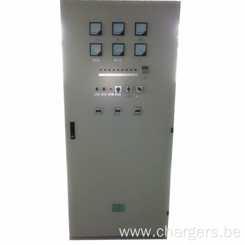
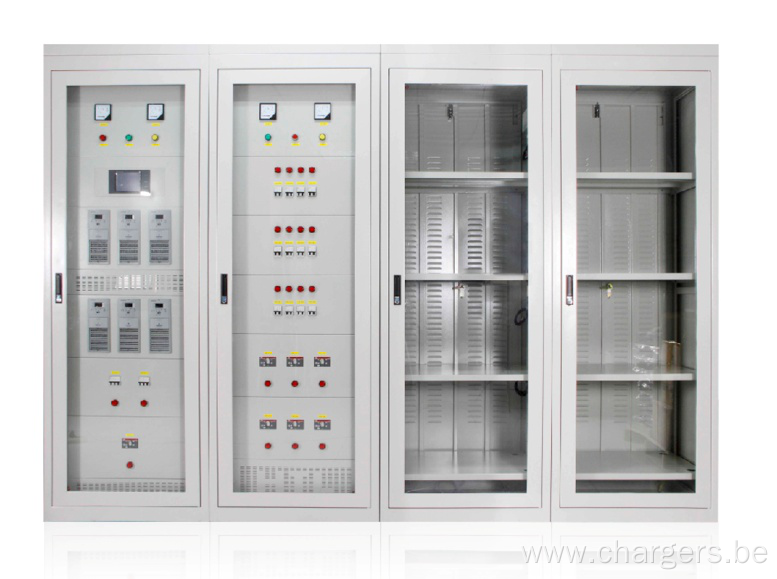
Instrument & Control:
Mains on/off input circuit breaker or switch
Boost/Float/Auto switch
Indicating LED
Voltmeter / Ammeter
Protection:
MCB or High-Speed fuse
- RC suppression for thyristor bridge
- Over voltage / Under voltage
-AC input surge suppressor
-Soft Start (Short circuit protection slow starts device)
-Total Current limit
-Control circuit & Voltmeter fuses
-Rectifier Protection fuses
Float Charge Nickel Cadmium Battery – 1.30V per cell This will enable the battery to recover its capacity quickly and reduce the water consumption. In this aspect, it will reduce the topping up frequency and storage of water. Boost Charge Nickel Cadmium Battery – 1.60 V per cell Equal Charge Nickel Cadmium Battery– 1.65 V per cell Optional Items Discharge tester and monitoring alarms can be added to the charger control board with no modification required. 2,Rectifier Circuit When the rectifier is connected to an appropriate AC voltage source, the voltage is connected to the input transformer. The current passes through an AC breaker. The transformer steps the voltage up or down, as required for the specific DC output voltage. The transformer also isolates the commercial AC line from the battery circuit. One of the secondary of the transformer is connected to the full wave bridge rectifier. Note that a RC surge suppressor is connected directly across the secondary. This provides protection for the bridge rectifiers against incoming AC line surges. The bridge is the heart of the power circuit. This assembly is a standard full wave silicon bridge, which is therefore capable of being made conductive for any part of each cycle. This is accomplished by the application of pulse to the gate of the terminal of the SCR at the desired time. Before the pulse is applied, the SCR is open, and no current flows in the circuit. However, as soon as the SCR is fired, it operates as a standard silicon rectifier until the forward current is reduced to almost zero. Charger output control can therefore be accomplished by changing the point in time the SCR are fired. The firing angle determines the output of the bridge. When α is large, the SCR conducts for only a short time, and the bridge output power is low. When α is small, the SCR conducts for nearly the complete cycle, and the bridge output power is high. As load increases, the conduction angle will decrease until the SCR is at full conduction. When the full load rating of the charger is exceeded, the firing angle is increased to the partial Conduction State. The control module plug in card accomplishes control of the SCR firing. Following the bridge is a snubber circuit, consisting of a resistor and capacitor. This acts to suppress DC line surges and thereby protect the bridge output. This acts to insure proper operation of the SCR and allows for full conduction when required. 3,Control Unit A plug-in printed circuit card is used for charger control. This solid state card which utilizes integrated circuits, provides the charger with voltage regulation and automatic current limiting by controlling the SCR conduction angle (α).The control circuit contains the following: Resistor Voltage Sensing Network A resistor divider network senses the battery voltage. The programmed resistor matches the card to the particular charger and the value of this resistor is selected according to the charger`s nominal output voltage. The output of the voltage-sensing network is fed to an integrated circuit, which generates an error signal. This error signal is used to vary the firing angle. Current Regulation The charger will change from voltage regulating to current regulating (current limiting) when the current regulator takes over control of the firing angle (α). In the current regulator, a reference voltage is compared with the voltage across the ammeter shunt. When the voltage reaches a preset value, the current limit circuit assumes control. Current limiting may be adjusted from 0 to 100% of the charger`s nominal output current. Voltage Regulation If the output voltage of the charge decreases, the voltage regulator will raise the output voltage. The voltage regulator and current regulator compare the voltage to a fixed reference. AC Power The printed circuit control module derives its power from a separate secondary transformer winding. This voltage is rectified by means of SCR, and provides the control circuit with DC power source. Slow Start Circuit When the charger is switch on with a completely discharge battery on the output, or short circuit, heavy current pulses can occur when the control circuit attempts to regulate the charger to full output. These current pulses can destroy the semiconductors in the bridge rectifier. To prevent this, the control circuit is equipped with a slow start circuit. This device consists of a capacitor that is rapidly discharged when the AC supply main voltage drops to zero. When the AC voltage returns, the capacitor is charged relatively slowly. The voltage across the capacitor affects the firing angle (α), so that the charger`s output increases slowly during the first 1–2 seconds of operation. Synchronizing Circuit In order to deliver the firing pulses to the SCR at the appropriate time for each cycle, it is necessary to synchronize the phase shift modulator to the incoming AC line. The synchronizing circuit accomplishes this. Product Categories : Battery Charger > Nickel Cadmium Battery Charger